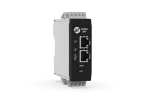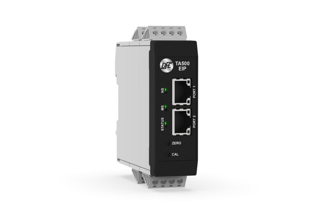
TA500 tension load cell amplifiers with EtherNet/IP™ or EtherCAT® connectivity are flagship interfaces capable of the highest resolution and response speed when paired with DFE tension transducers. There are multiple implementation methods that can be used to scale the device output values in a PLC. This article will focus on utilizing the 16-bit ADC values directly from the device to deliver maximum load cell resolution.
BASIC DEVICE ARCHITECTURE
The TA500 employs the use of a 24-bit ADC that downsamples to 16-bit in real-time, delivering noise-free performance without delay. This is achieved at low gain levels due to the high dynamic range of DFE’s semiconductor strain gauge load cells. The TA500 also provides analog outputs (0-10 VDC and 4-20 mA) scaled down to 12-bit resolution via onboard DAC.
In a typical use-case, DFE applications engineers will size load cells to achieve the highest possible resolution within the physical constraints of the application. Factors such as idler weight, tension range, wrap angle and force direction all play a role in determining the overall utilization of the transducer. By predicting load cell output in mV terms, DFE sizing tools can provide an estimate for amplifier resolution at both the 12-bit analog outputs and 16-bit ADC. In some challenging applications, range constraints caused by odd force angles or heavy roll weights can deliver similar 12 and 16-bit performance (ie., 4096 vs 5140 discrete steps). However, in most applications, a 2X to 8X improvement in resolution can be experienced by directly accessing the 16-bit ADC values, as shown in Figure 1 below.
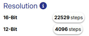 Figure 1 – Typical resolution for Ethernet (16-bit) and analog (12-bit) connections from the DFE transducer sizing calculator
BASIC CALIBRATION METHOD
The simplest way to calibrate DFE load cells with the TA500 amplifier is to use the physical Zero and Cal buttons located on the front of the device. After performing the calibration procedure (as described in the manual), a range of values will be stored in the device as Tags/PDOs that can be accessed over Ethernet.
After calibration, the most common method for accessing the tension range of the device over Ethernet is by way of the TENSION_P Tag. The TENSION_P Tag is scaled to 0.1% resolution which is equivalent to 0-1000 in integer terms. As a result, scaling the values in a PLC is a very straightforward process. If a 5 lb weight is used for the 10% calibration procedure, the measurement range will scale to 0-50 lbs and the integer span will equate to a resolution of 0.05 lb.
ADVANCED CALIBRATION METHOD
Achieving the maximum performance of the device is slightly more involved, but not overly difficult. During calibration, additional values are stored in the device in the ACTIVE_ZCODE and ACTIVE_SCODE registers. These are integer values derived from the 16-bit ADC which spans 0-65,535.
Using the resolution chart in Figure 1 as an example, let’s surmise that the active ADC_VALUE at Zero position registers 18,500.0. When the Zero button is pressed, that value will be stored in the ACTIVE_ZCODE register. Next, the 10% calibration weight will be hung across the load cell system. This will result in the ADC_VALUE moving up by 2,252.9 points. Finally, when the Cal button is depressed, 2,252.9 will be multiplied by 10 and the value 22,529 will be stored to the ACTIVE_SCODE, representing the full measurement span in integer terms.
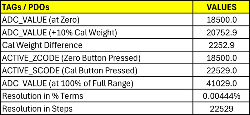
Figure 2 – Example of the progression of 16-bit ADC values during the calibration process
After following the installation procedure in the manual for the applicable EDS or ESI file, commands can also be sent through the PLC interface to store or retrieve ADC_VALUE, ACTIVE_ZCODE and ACTIVE_SCODE values shown in Figure 2.
CONCLUSION
While actual performance gains must be realized on a case-by-case basis as defined by the application constraints, in most cases utilizing the advanced calibration method opens up significantly more system resolution. In the example above, tapping the ADC values directly provides more than a 5X advantage over the 12-bit analog outputs and a 22X advantage over implementing the 0.1% TENSION_P Tag approach. The TA500 series of tension amplifiers are compatible with all DFE load cells manufactured since the early 1980s, so a substantial increase in performance can be had by simply upgrading older DFE amplifiers to the new flagship.
EtherNet/IP™ is a trademark of ODVA, Inc.
EtherCAT® is a registered trademark and patented technology, licensed by Beckhoff Automation GmbH, Germany.