In recent years manufacturers and converters of extensible materials have been seeking the capability to measure and control process tension on two or more parallel web sections. In response, DFE has expanded upon the design of the popular Tension Roll® Transducer to deliver a custom device with multiple tension-sensing roll segments assembled in a series on a single shaft.
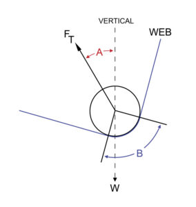
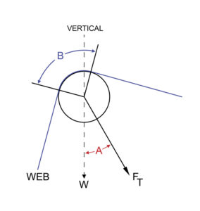
The Segmented Tension Roll® Transducer‘s compact footprint allows the same web path to be used for tension measurement of multiple web strands. This space savings and convenience simplifies the integration task of mechanical designers and process engineering teams. Each tension roll segment is also capable of measuring force bidirectionally and being calibrated independently, which affords additional flexibility with the routing of web paths. Now individual webs can be routed over or under each roll segment in infinite combinations.
UNIQUE APPLICATIONS
In some applications the Segmented Tension Roll® has been used to measure multiple data points across a continuous web width. This allows producers and converters to quickly inspect and profile many types of materials such as paper, film and foil. Combined with data logging devices, STR transducers have even been used to optimize the rotational speed of blown film extrusion dies to achieve thickness uniformity of product.
HOW IT WORKS
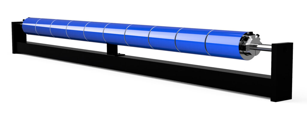
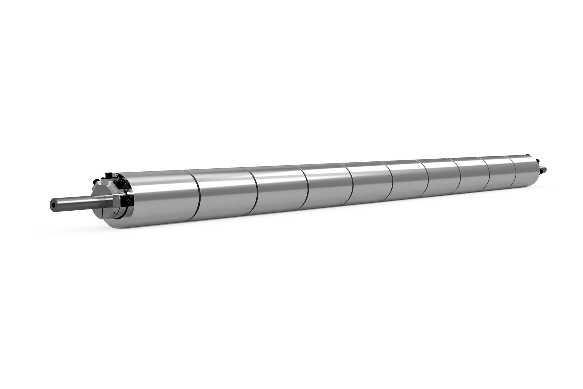
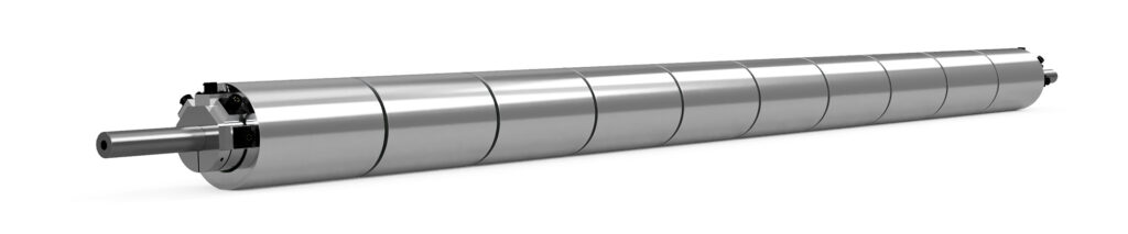
A typical Segmented Tension Roll® transducer consists of a single shaft with a series of evenly spaced tension-sensing idler roll segments. Each roll segment has integrated semiconductor strain gauge tension sensors in both ends. Electrical connectors are installed on the shaft ends and numbered accordingly for ease of identification and calibration. The standard roll type is aluminum with a 16 Ra or better finish. Other finishes and coatings are available by request.
The STR assembly can be mounted in a carrier frame with support brackets to minimize shaft deflection and accommodate higher load ratings. Two system ‘sizes’ are available – 1 and 2. The size 1 STR has a 3-inch diameter roll and 1-inch diameter shaft, while the size 2 has a 4-inch diameter roll and 1.125-inch shaft. The maximum number of segments is limited to five for 3-inch diameter systems and ten for 4-inch to 6-inch diameter systems. The maximum shaft length of an STR is 120 inches.
As with our standard Tension Roll® transducers, the ordering process is straightforward. To request a quotation you’ll need to specify your desired overall shaft length, roll diameter, roll segment length, gap between segments and load rating per segment. Shaft support brackets and frames can be supplied by DFE or the customer and should be specified at the time of quote.
Each Segmented Tension Roll® is made to order, so please consult your DFE sales engineer for help with load qualification or to check availability of special coatings or finishes prior to ordering.
FEATURES & BENEFITS
• 5 year tension-free warranty
• Highly accurate and reliable semiconductor strain gauge technology
• Measure tension on parallel web strands or at multiple points across a web width
• Choose length to fit machine or press frame
• 50:1 Effective load sensing range
• Combined load rating up to 400 lbs (1800 N)