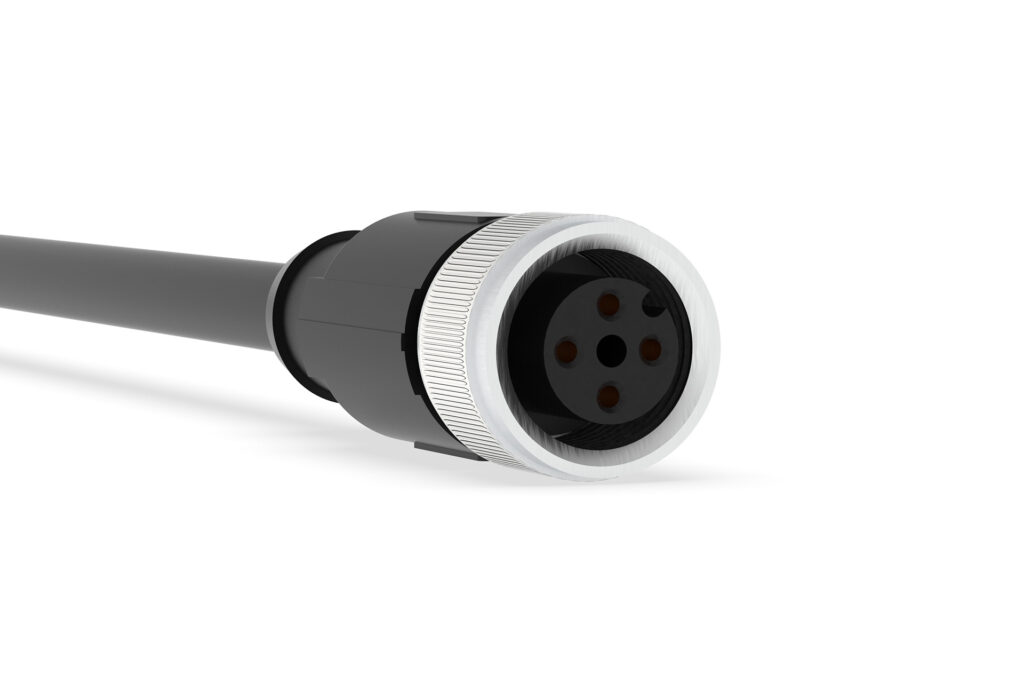
Load Cell Cables (M12)
Robust cables with M12 connectors, designed to connect DFE tension load cells with amplifiers, display indicators or closed-loop controllers.
M12 load cell cables are abrasion-resistant and shielded to minimize wear and prevent electromagnetic interference. Sealed, IP65/IP67 connectors prevent corrosion of contacts and ingress of contaminants while operating in harsh environments.
FEATURES & BENEFITS
• Fits Model C transducers with optional M12 connector
Note: Select mil-spec cables for standard connector
• Certified for use with DFE high-output semiconductor strain gauge load cells
• Shielded to resist electromagnetic interference
• Sealed connectors rated for harsh environments
• Polyurethane jacketed to resist abrasion and moisture
• 1 year warranty against defects
Do you have more questions about this product?
Complete the form below and a DFE Applications Engineer will contact you shortly.
DFE does not share information with 3rd party advertisers.
Wire Configuration: 4 Conductor
Conductor Type: Tinned Copper
Conductor Size: 22 AWG
Shielding: Braid, Foil
Jacket Material: PUR Halogen-Free, Black
Voltage Rating: 60 VDC
Temperature Range: -20° to 80° C
4-Socket to Flying-Leads Cable
Connects Model C load cells with M12 bulkhead connector to devices with a terminal block
16.4 Ft (5 m) Long – P/N: 131-0102
32.8 Ft (10 m) Long – P/N: 131-0099
49.2 Ft (15 m) Long – P/N: 131-0101
REFERENCE DOCUMENTS
Load Cell Cable Data Sheet
Click the preferred product in the table below, then select CAD format to download.
Note: M12 cables are only compatible with Model C transducers with the M12 connector option.
Complete the form to enable your file download
| Product Code | Length | Load Cell End | Interface End |
| 131-0102 | 16.4 ft (5 m) | 4 Socket Connector | Flying Leads |
| 131-0099 | 32.8 ft (10 m) | 4 Socket Connector | Flying Leads |
| 131-0101 | 49.2 ft (15 m) | 4 Socket Connector | Flying Leads |
Complete the form below and a DFE Applications Engineer will contact you shortly.
DFE does not share information with 3rd party advertisers.
To test continuity, probe the connector sockets and associated wire colors as listed below –
| Connector Socket Number | Wire Color |
| Socket 1 | Brown |
| Socket 2 | White |
| Socket 3 | Blue |
| Socket 4 | Black |

