The manufacture of converting machinery with multiple web paths able to support a wide range of processing requirements has become more popular than ever. While some machines may require separate tension control systems to support isolated web paths (geometry can be a stubborn thing), some designers may be able to consolidate their tension system by taking advantage of the high dynamic range and bidirectional sensing capability of DFE load cells.
Take for example the hypothetical scenario involving two web paths shown in Figure 1. Wrap A is utilized for a full-width, non-extensible film with a setpoint of 100 lbs of tension. In contrast, Wrap B is utilized for a narrow, extensible film with a setpoint of 10 lbs of tension.
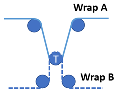
Figure 1 – Opposing Web Paths
In the Wrap A web path, resultant force is directed upward, subtracting idler roll weight. The wrap on the contact surface of the Tension Roll is 150 degrees, resulting in approximately 180 lbs of Net force.
In Wrap B, resultant force is downward in the opposite direction. While the wrap angle is more aggressive at 180 degrees, the resulting Net force is only 30 lbs.
This 6:1 difference in measurement range, with opposing force directions, would normally be a deal-breaker for many traditional tension measurement systems. Fortunately, it is possible to overcome this challenge by using a feature available in DFE amplifiers known as Dual Calibration.
DUAL CALIBRATION VIA HARDWARE
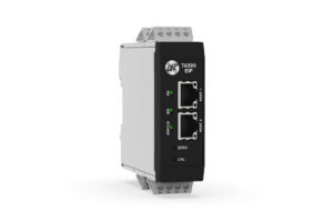
Dual Calibration exists as a hardware function in DFE’s TA1 tension amplifier. During the Zero and Calibration procedure, circuit closure to PIN 6 enables storage of a second calibration profile. This Cal B profile, effectively rescales the load cell offset, allowing for operation in the opposite force direction while also applying full scale gain in the amplifier. This delivers a boost to signal output resolution, allowing it to reach its theoretical max. In practice, recalling Cal B is as simple as activating the same circuit closure, which makes accessing the feature from a PLC an easy task to accomplish.
While the simplicity of analog circuits is sometimes preferable, the growing popularity of Ethernet bus means an equivalent solution must also be available that can deliver the same benefits.
DUAL CALIBRATION OVER ETHERNET
The TA500 tension amplifier expands on the TA1’s capability by adding more flexibility, with calibration that is orchestrated via the EtherNet/IPTM interface at the machine PLC level. A provided EDS file is loaded into Studio 5000 environments and commands are sent to the TA500 using basic ‘MOV’ instructions. Just like the TA1, the amplifier attached to the transducer represented in Figure 1 must be calibrated for opposing web paths. To accomplish this, separate two-point calibration values must be stored in the PLC. These offsets can be assigned later to coincide with the proper machine setup.
The complete TA500 calibration procedure is available to review here.
The TA500 accurately indicates tension with resolution of 0.1% of full-scale range. This tension data is updated every 10mS. The data is available in the tag “TA500_InData.TENSION_P” which is automatically available if the provided EDS has been loaded properly.
Before we can calibrate for Wrap B we must store two calibration values from the TA500 in “TA500_InData.ACTIVE_ZCODE” and “TA500_InData.ACTIVE_SCODE”. These values are the two-point calibration values required to restore the Wrap A calibration, when needed. While saving these values to the PLC, the user can also opt to save a range value associated with the calibration being stored in the PLC.
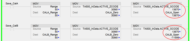
Figure 2 – Ladder logic showing active 2-point calibration values for Cal A and Cal B
Once these values are stored, we can move on to calibrating the Wrap B web path. After performing the same procedure for the second wrap angle, the same logic applies to storing the calibration values. As shown in Figure 2, the Span code polarity has effectively flipped as compared to the values stored for Cal A. This drastic difference in values corresponds correctly with resulting force from tension acting on both sides of the load cell and is confirmation that the procedure was successful.
We now have two unique calibrated web paths with locally stored calibration values in the PLC, so operating the machine in harmony with either web path can be easily accomplished by updating the amplifier and its corresponding calibration values. This process is completed by moving the ‘Zero Value’ and ‘Span Value’ for the desired calibration into the tags “TA500_OutData.ZERO_VALUE” and “TA500_OutData.SPAN_VALUE” tags and then issuing a “Set Gain” command to restore the calibration. Note the ladder logic shown in Figure 3.
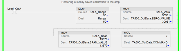
Figure 3 – Restoring a saved calibration
GREATER FLEXIBILITY & PERFORMANCE
In summary, controlling multiple calibrations at the PLC level allows machine builders greater flexibility with setup configurations for multiple web paths, without the need to purchase separate load cells systems for different use cases. The high output of DFE’s bidirectional, semiconductor strain gauge load cells enable users to tackle a wide range of job requirements with ease. Independent amplifier calibration for different web paths optimizes DFE load cell performance by scaling amplifier gain with DAC output resolution to achieve maximum system performance.
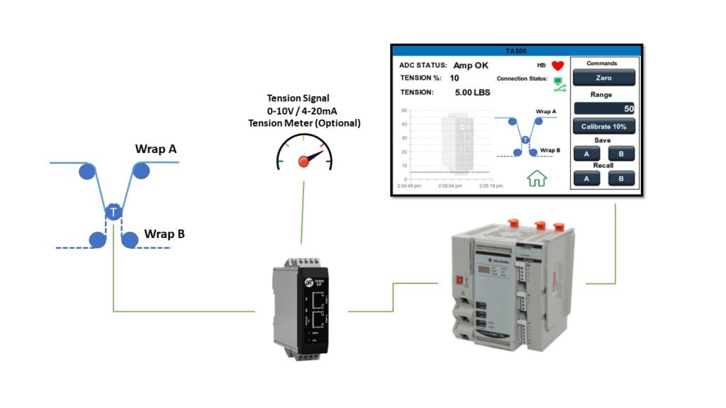
Figure 4 – An example of a dynamic machine configuration for toggling amplifier gain
For more information about features such as Cal A/B in the TA1 or gain programming in the TA500, contact DFE Sales or Tech Support.