SILICON-TYPE VS FOIL-TYPE STRAIN GAUGES
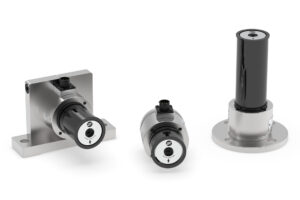
DFE has been producing high-quality strain gauge tension load cells (also called transducers) since 1984. Web material manufacturers, converters and OEMs buy DFE tension load cells because they are accurate, long-lasting, reliable and virtually maintenance-free.
DFE uses a silicon-type semiconductor strain gauge as the transducer tension-sensing element because of the gauge’s proven resolution, durability, longevity and low-noise output. The alternative, a foil-type strain gauge, is used by some of our competitors. Although a much older technology, foil strain gauges enjoy continuing popularity because of their widespread availability and low manufacturing cost.
STRAIN GAUGES AND DRIFT
Transducers are typically not used as tension sensors in isolation but are components of a measurement system with the load cell output signal being amplified and often observed on a readout display of an indication device or controller. What is commonly referred to as “drift” is also known as “null displacement” or “zero shift”. It is a change in the tension load cell’s no-load output signal over time. The ‘drift’ we sometimes see when looking at zero tension on an unloaded transducer is manifested as a slight offset from the zero point on the output device’s meter.
Zero-shift error is a common condition that is easily corrected for and does not suggest flawed performance from a load cell. An observed meter scale offset from zero can be corrected simply by resetting the amplifier’s ZERO adjustment. Some load cell manufacturers contend that the zero shift condition can and should be corrected by completely recalibrating the amplifier to the transducer. However, complete recalibration is rarely necessary. When an amplifier/indicator device is originally calibrated to operate with a load cell, the effective measurement range does not change even if a zero shift occurs over time. For instance, if the tension meter were calibrated for a 50 lb range, the range is still 50 lbs even if the output with no load on the transducer has moved from zero. The entire 50 lb range has simply shifted upscale or downscale by a small amount.
ZERO-SHIFT CAUSES
Zero-shift effects can be caused by one or more of these factors:
Preloading. Incorrect installation of the transducers can result in a preload on the sensing beams. This is very common and is not a shortcoming of the transducer. Drift from preloading can be very serious. Fortunately, eliminating the preload condition can usually be accomplished with an installation adjustment.
According to Dover Flexo’s Technical Support Team, transducer preloading is the most common cause of reported zero shift. DFE load cells are designed with a coupling that minimizes the likelihood of incorrect installation. DFE couplings also prevent the type of mechanical binding that may occur in older or rudimentary designs that do not compensate for thermal expansion of roller shafts.
Stress relief. The sensing-beam metal is stress relieving over time. This usually finishes within 1-2 weeks after first use. The gauge detects the changes of strain in the metal and thinks it is an applied load. This observed effect is relatively small unless the beam is made from a material unsuitable for strain gauge use.
Final curing. The final stage of gauge adhesive curing is occurring. This typically ends 2-3 weeks after the strain gauge is applied. This is also a small effect but greater than the stress relief effect.
Incidental contact. Something is touching the transducer roll other than the web. Perhaps a gear is installed on the shaft, or a pulley and belt, or the roll is filled with water, etc. For any transducer to output an accurate tension signal, nothing but the web must contact the roll and nothing can contact the shaft.
Electronic problems or wiring errors. Power supply or amplifier circuitry drifting may appear to be zero shift. Faulty ground connections can allow the electronics to drift. DFE’s second-generation Quik-CalTM digital calibration circuitry with built-in diagnostics can detect these problems in real-time.
Ambient temperature variation. This is an issue for all load cells regardless of the type of strain gauge. It also affects the magneto-elastic and LVDT-type transducers. DFE has taken special care to minimize the effects of temperature variation with proprietary design and manufacturing techniques.
CRITICISM OF SILICON STRAIN GAUGES MADE BY SOME COMPETITORS
1. Some competitors infer that silicon strain gauges with high temperature coefficient specs are representative of DFE strain gauges. This is not true. Silicon strain gauges are wildly diverse in their attributes. DFE gauges are application-specific, to achieve the performance described in our data sheets.
2. Zero shift from temperature variation is not a problem for most applications. Only processes incurring very wide temperature swings exhibit drift to any meaningful extent, and these situations can be mitigated with simple shielding techniques or directed ventilation. Temperature-induced zero shift rarely affects the quality of the product being processed.
3. Competitor advertising touting less drift is actually a tempest in a teacup, as achieving total elimination of drift, present inside of a minute range, would still have a negligible impact on process quality. Ironically, many foil gauge load cells that advertise low drift also happen to be low signal output designs, making it difficult for the load cells to detect changes at the lower end of the tension range, closest to the noise floor.
THE MOST IMPORTANT DIFFERENCES BETWEEN FOIL AND SEMICONDUCTOR STRAIN GAUGES
While functionally similar (in that they each demonstrate a resistance change under an applied strain), there are two major differences between silicon and foil strain gauges:
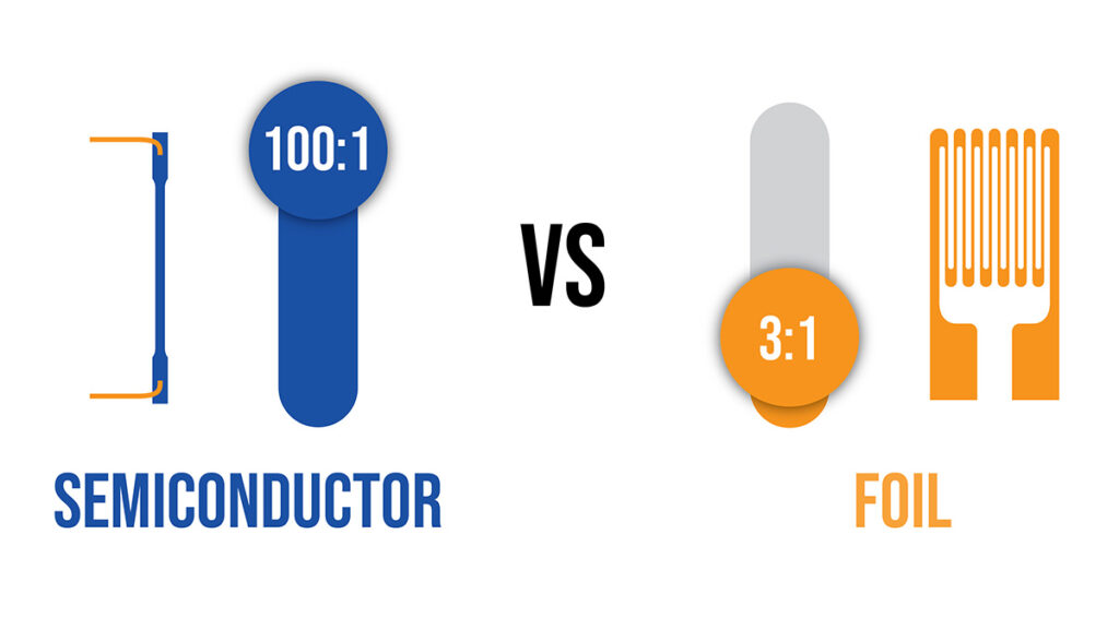
1. Semiconductor gauges have electrical outputs relative to strain applied that are 25 to 50 times that of foil gauges.
2. The available geometries of silicon gauges are typically small, simple straight strips. Metal foil gauges are configured in various complex 2-dimensional patterns. This increases the area exposed to applied strain in order to boost the signal output.
How do these differences affect load cell design and performance?
Overload Protection. The greater sensitivity (larger output) of silicon gauges means that less stress is needed to produce a usable amount of signal, and therefore a transducer’s bending beam can be built more robustly and better protected from overload than beams with foil gauges. Load cells designed with silicon gauges are typically highly reliable, long-lasting and trouble-free.
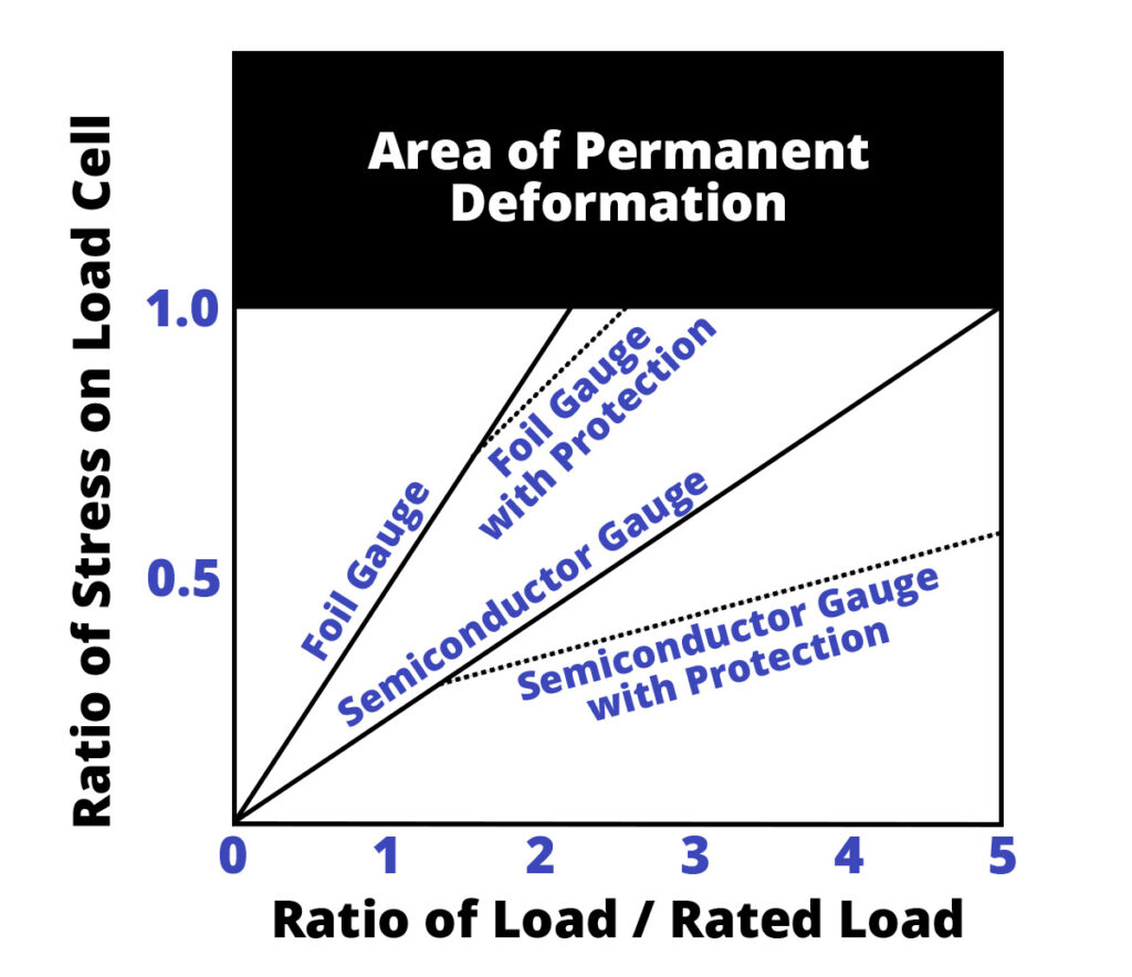
Chart courtesy of Mr. Robert Little, ATI Industrial Automation
With their lower sensitivity, foil gauge load cells must operate close to the gauge yield point (point of permanent deformation) at load in order to deliver a usable amount of signal. Therefore their beams are designed to bend more and, as a consequence, are less forgiving of overloads.
Fatigue Life. Silicon-type semiconductor strain gauges have an extremely long fatigue life as compared to foil gauges. This is an important issue for tension transducers, which are sometimes operated continuously for up to 3 shifts per day. As a result of operating near their yield points, foil gauges suffer from shortened life spans and fatigue life when compared to silicon gauges. As a quick mental exercise, have you ever seen an industrial foil gauge load cell with more than a 1 year warranty?
Low tension output and extended range. The larger signal output from silicon gauges allows measurement of very low tensions. Load cells with foil gauges have difficulty with low tensions because the nominal output is so low it can be lost in the ambient electronic noise present in the electrical system. Not so with silicon gauges. Even at relatively low tensions the output is strong and usable. The higher output magnitude also makes it possible for transducer signals to be brought directly into PLC inputs, lowering system costs. Load cells built with silicon gauges simply have a broader operating range.
Electronic noise and interference. The low output of foil gauge transducers requires associated amplifier electronics to have a much higher gain for the amplified signal to be useful. The high gain makes the system much more susceptible to EMI and RF noise. Sudden changes in tension resulting from electronic transients can create wasted product if the tension signal is part of a closed-loop control system.
Gage Creep. When foil gauge beams are manufactured, the thin foil gauges are typically adhered to a thin organic substrate, which is then adhered to the transducer beam. So there are two layers of adhesive and one layer of substrate between the gauge and the beam. Silicon gauge transducers use only one thin layer of adhesive between the gauge and the beam. This makes silicon gauges much less susceptible to gauge creep (drifting output over time) and non-repeatability. Transducers using silicon gauges tend to maintain better accuracy over the long-term.
Hysteresis. Silicon gauge load cells exhibit less hysteresis than foil gauge load cells and are therefore more repeatable. The hysteresis effect can be described as an offset in measured output (voltage) for two different occurrences of the same input value (i.e. tension). Hysteresis can be measured by measuring device output as we approach a given input value from opposite directions (i.e. increasing and decreasing tension).
For example, let’s consider a transducer loaded to 40 lbs and producing 115 mV output. If we apply 50 more lbs and then remove the 50 lbs a transducer with no hysteresis will return exactly to 115 mV output. Take away 20 lbs and then add it back. Output should be 115 mV if there is no hysteresis. If the transducer shows hysteresis, the output might go to 120 mV in the first case and 100 mV in the second case. Obviously, significant hysteresis is undesirable because it affects measurement accuracy.
OTHER MISLEADING ADVERTISING CLAIMS
It seems, in the crowded and maturing tension control industry, foil gauge load cell manufacturers are clutching at straws to enhance their product benefits.
Some competitors and foil gauge advocates claim that silicon strain gauges “can be severely affected by temperature, steam, corrosive gases, chemicals and many other common contaminants.” But in reality, any type of strain gauge is affected by these factors. Therefore, each manufacturer applies a protective coating such as RTV over the gauges for protection. No manufacturer of transducers that we know of uses unprotected gauges of any type. This is just another misleading, unfounded claim for marketing purposes.
Some manufacturers of foil gauge load cells also highlight their use of a “full wheatstone bridge” electronic configuration as a major competitive strength. What they fail to mention is that they must use this configuration in order to generate a sufficient output signal. Foil gauge technology doesn’t offer any improvement over DFE’s transducers because we also employ a full wheatstone bridge.
CONCLUSION
For the reasons previously described, thermal drift benefits marketed by some foil gauge competitors is misinformed and not significant in real-world applications. Foil gauge load cell manufacturers benefit mostly from reduced cost, higher availability of components and easier assembly, which translates into greater profits at the expense of performance.
Compared directly, load cells made with semiconductor gauges are stronger, more accurate and longer-lasting. They are less susceptible to electrical noise and provide dramatically better signal output. These characteristics ensure that DFE load cells are able to deliver a significantly wider tension range with better low-end sensitivity.
The use of silicon strain gauges, together with sophisticated structural engineering is the reason DFE is able to offer an industry-leading 5 year warranty, while most competitors are only comfortable providing a year or less.