In web converting, one of the most crucial areas to control tension is in intermediate process zones. Intermediate zones can involve processes such as coating, drying, treating, laminating, printing, curing, slitting and more. During processing, material characteristics can shift based on the type of converting being performed. For example, a material with a coating applied may become more prone to stretching, requiring a reduced tension setpoint as compared to the base substrate. Further down the line, the same material may become more prone to wrinkling or shrinking during a drying stage, requiring an increase in tension to compensate.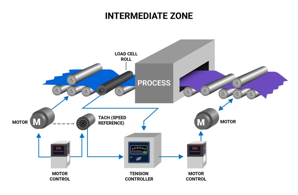 In these situations, simply maintaining speed between zones may not be enough to ensure sufficient quality. While it may be possible to experiment and improve quality by manually adjusting drives, having the ability to actually observe tension opens the door to documenting setpoints that can be maintained via dynamic control, ensuring repeatable results.
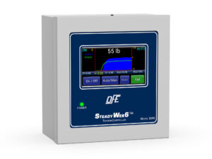
The SteadyWeb 6™ closed-loop tension controller has been designed to effectively control intermediate zones by simultaneously observing line speed and tension feedback. In practice, the controller monitors a line speed reference signal from an upstream tach or speed master and increases or reduces the speed of a downstream driven roll or nip to maintain a tension setpoint.
Configuring the controller requires a few simple steps. First, the tension zone must be set to Intermediate in the Tension Control Setup menu screen.
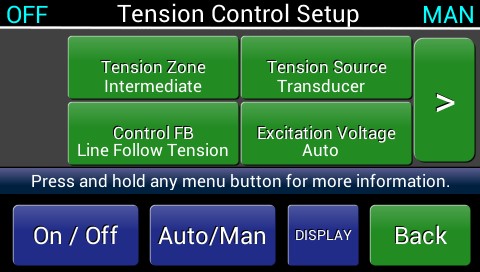
Next, Line Follow Tension feedback control mode must be selected (see screen above). This mode overrides the default closed-loop algorithm that is more applicable to torque-controlled unwind or rewind zones.
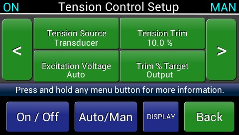
While in the Tension Control Setup menu, check to confirm that Tension Trim is set to the default of 10% (see screen above). This parameter can be increased or decreased as required while tuning, however it is suggested not to exceed 20% tension trim.
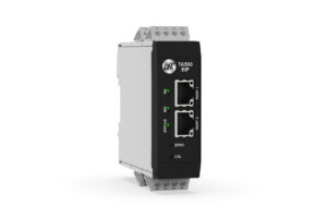
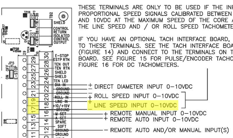
Next, the upstream speed reference signal must be connected to the appropriate tension controller input terminal. The default input accepts a 0-10V signal (see diagram below), however, additional input cards can be selected that support pulse tachs (encoders) or DC tachs of a wider voltage range.
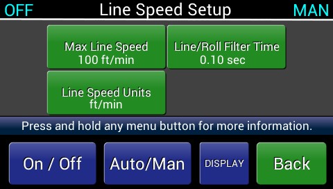
After the line speed connection has been established, the input will need to be calibrated to match the appropriate line speed range. This is accomplished in the Line Speed Setup menu screen (see screen below). This screen allows the user to define the Line Speed Units of measure, Max Line Speed (corresponding speed at maximum voltage or pulse rate) and Line/Roll Filter Time.
Once Line Speed Setup is complete, all load cell input connections should be confirmed (or secured), and the controller Zero and Calibration steps should be performed as described on page 51 of the instruction manual. After load cell calibration is complete the system is ready to run.
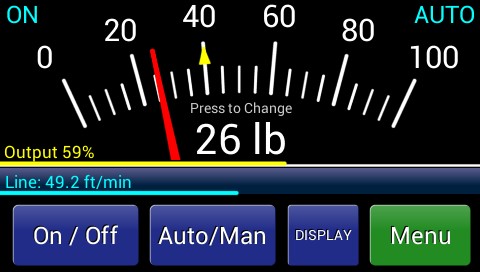
During operation, the line speed reference will be visible on the lower left quadrant of the main operator screen (see screen above). This visual cue is confirmation that the controller is setup in the correct control mode and will be able to adjust tension in harmony with line speed. In Line Follow Tension mode, the SteadyWeb 6™ controller will automatically increase or decrease output to the downstream drive by up to 20% to maintain the selected tension setpoint. As previously mentioned, the Tension Trim setting in the Tension Control Setup menu can be adjusted to tune the system further during operation.
If the line speed indicator displays cyclic fluctuations, it is possible to dampen the incoming signal by increasing the Line/Roll Filter Time in the Line Speed Setup Menu. This will prevent the controller from oscillating as it attempts to error correct. Conversely, if line speed indication is stable but response is slow, decreasing the Line/Roll Filter Time will increase controller responsiveness to changes in line speed.
Congratulations on properly configuring your intermediate tension control system. After experiencing the quality and performance benefits that proper web tension control provides, we’re sure you’ll agree its an investment that was well worth the time and money!
Typical intermediate tension control solutions incorporate:
• A closed-loop tension controller such as the SteadyWeb™ 6
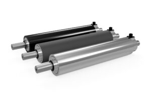
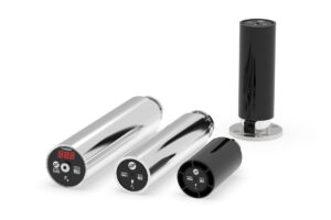
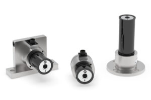
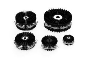
• A load cell such as the Tension Roll® Transducer
• A Motor Drive System