What do we mean by ‘Tension Control’?
The term “tension control” as applied to materials processing, refers to the dynamic control of tension on a web being pulled through a machine’s processing zone.
Tension is created either by a tensioning device pulling (usually a driven nip, lay-on roll or winder) on the web at one end (rewind or intermediate zone), or by increasing the drag at the other end with a brake or regenerative drive (unwind zone).
With a manual control system, web tension is measured by a device, like a tension transducer, and then made available for read-out on a meter or other type of display. The machine operator looks at the measured tension on the meter and then makes manual adjustments to a tensioning device to bring the actual web tension close to the desired value.

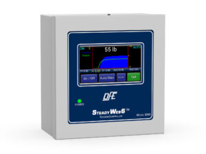
SteadyWeb 6™ Closed-Loop Tension Controller
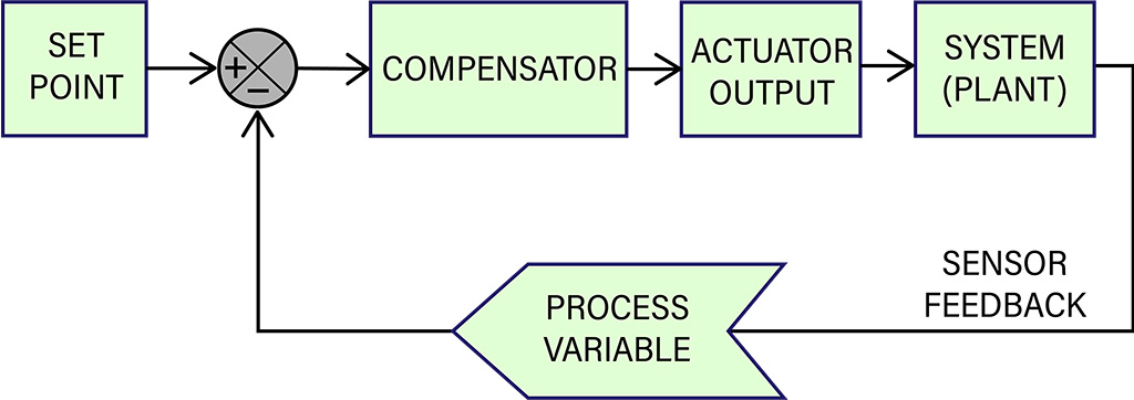
A closed-loop electronic control system can provide far greater accuracy and repeatability than a manual open-loop system. In a closed-loop control system, we replace the operator’s judgment and intuition about how much to adjust a tensioning device’s output with an electronic controller’s control algorithm.
In a closed-loop system, the process variable (web tension in our case) in a particular zone of the process is measured many times a second. The controller’s output to the tensioning device is adjusted at a constant loop rate in response to the error signal generated as the controller compares the measured tension value to a desired reference (set point).
Tension Measurement and Automatic closed-loop PID Control
The appropriate running tension is usually pre-determined based on what works best for a particular web substrate in a given process (see Product Guide for suggestions on typical tensions for various substrates).
The machine operator enters the tension set point into the controller when setting up the job run.
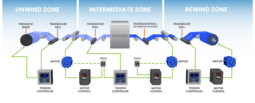
Tension Control Zones
Then, as the web machine runs, tension on the transducer-equipped idler roller is measured and read by the controller. A special comparison circuit looks at both the set point and the actual measured web tension, the difference of which is an error signal.
Because web processes are dynamic systems, tension in any zone tends to change from moment to moment, typically running less than or greater than our desired tension.
The aim of our controller circuitry is to output a compensating (corrective) signal based on the error signal, and for the tensioning mechanism to adjust the web tension toward our set point value.
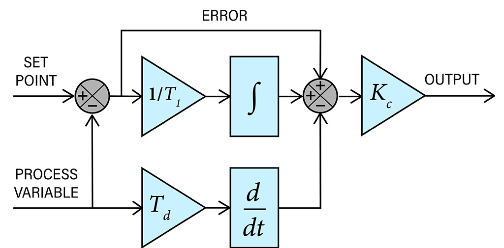
All of DFE’s automatic tension controllers use the Proportional-Integral-Derivative (PID) control algorithm. There are other algorithms, but PID is the most common for industrial applications due to its robust performance in a wide range of operating conditions.
P + I + D: The Corrective Actions of a Tension Controller
The basic concept of a PID control algorithm is for the controller to read the tension transducer (load cell) signal, then compute the desired output to the tensioning mechanism by calculating proportional, integral and derivative responses and summing the three components to arrive at a final output.
Proportional Action: The ‘P’ of PID
The ‘I’ gain circuitry acts to size the correction signal (either in-creasing or decreasing tension) to keep it proportional in magnitude to the original error signal. As the error signal changes, the resulting correction signal changes by the same factor. This proportional change of the correction signal is the ‘P’ of PID.
Determining the correct amount of gain to apply depends on how much deviation from the set point we expect from the process.
Large deviations produce a large error signal and therefore require less gain. Smaller deviations produce smaller error signals and therefore require more gain in order to produce a significant correction signal.
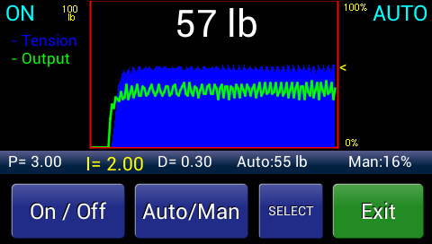
An Example of Tension Overshoot
Derivative Action: The ‘D’ of PID
As you may have experienced, the tighter the tolerance in which you try to control something, the harder it is to hold. Imagine an automobile cruise control set to a speed difference of +/- 0.1 miles per hour. It would constantly be turning off and on, and overshooting the set speed. The same effect would happen with tension control without the ‘I’ and the ‘D’ of PID.
In a mechanical, dynamic control system, there are many actions, reactions and changes occurring continuously. These have to be dealt with as the web moves through its process. A mass (rolls, rollers, web, motor armature, etc.) has to be accelerated and decelerated in response to system changes and constant modifications to the drive system are required as a roll builds up from core or down from full roll.
Let’s first address the acceleration dilemma.
The derivative component of a PID controller monitors the rate at which the tension error is changing. It is only interested in how fast the error signal is changing, not its absolute size. The correction signal output by the derivative circuit changes as long as the magnitude of the error signal is changing.
The derivative response is proportional to the rate of change of the tension error signal, such that when there is no error signal change its output is zero. When the machine starts, the web in the process has to go from zero speed to its final speed. The tension builds up, and a corresponding correction signal from our derivative circuit is applied. The added derivative signal makes the tension signal look larger then it really is, thus causing more brake to be applied before reaching the desired tension. This is what we want.
As the tension approaches the desired value and the brakes are gradually applied, the rate of change in tension decreases, thereby lowering the derivative output being added on. The actual tension will approach the desired tension at an increasingly slower rate until the two meet. At this point the derivative signal will be zero because the actual and desired tension values match.
Another way of looking at derivative action is that when the error signal changes, derivative action causes the controller gain to move the wrong way as the measured tension approaches the set point. This is different from the proportional circuit that re-acts only to the absolute error signal at any given moment in time.
Derivative action automatically adjusts for tension deviations in either direction, and it is used primarily to avoid and minimize overshoot.
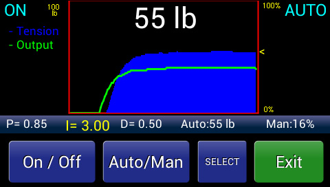
Controller Tuned for Rapid Response
Integral Action: The ‘I’ of PID
Let’s look at another analogy to consider Integral action. The integral component of PID control is probably something that could help us when we are in the shower adjusting the temperature to where we like it. When trying to regulate the water temperature, do you ever overreact? When the water is too hot do you turn the knob back only to find that you went too far? Back and forth it goes, until you finally reach a point where you are some-what satisfied.
Is the delayed result of your action due to the water temperature responding too slowly to the control? Or, all things being relative, are you turning the control too fast for the temperature to keep up with the change? The answer is that both ways of looking at the problem are correct. Each perspective just requires a different approach to solving the problem. The first perspective describes the problem from the approach that makes derivative pre-action look like the solution. The second perspective makes integral action (an offsetting, damping effect) look like a better approach. Fortunately a PID controller does both. It works both ends of the problem at once.
Let’s go back to the tension controller. Like the derivative circuit, the integrator circuit also reads tension error trend. But instead of providing an early output signal (phase lead) to improve tension response in direct reaction to the trend, the integrator gives a correction output that acts to smooth or, in effect, damp the rate of controller output so that the tensioning mechanism will not overreact.
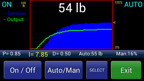
Controller Tuned for Slower Response
It’s like the person in the shower turning the knob more slowly so that the temperature change can keep up with the control change. This is just another way of adding stability to our system.
By combining both the early-responding derivative action and the smoothing-output integral action we can gain an acceptable level of dynamic response and stability.
In the case of most PID controllers, the P, I, and D components are all combined to produce one output signal. The effect from each action is adjusted during system setup and tuning, and varies depending upon the system parameters.
You’ll notice on DFE automatic tension controllers that we refer to the P-I-D components as “gain”, “stability”, and “response”. We find these terms are more descriptive and useful for customers than Proportional, Integral, and Derivative.