Transducer / Load Cell and Cable Testing
How to determine if a DFE cable or transducer is faulty.
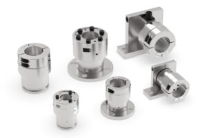
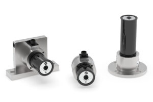
Model C, Model F, Model UPB, Model SUPB, Model RS Transducer (3 Pin)
To verify load cell integrity, unplug the transducer cable at the controller/indicator and use an ohm-meter to measure the resistance at the connector on the cable. Measure between pins A,B, and A,C. In each case, the resistance should be about 100 ohms (100 ohms nominal w/Std excitation, 200 ohms nominal w/XR excitation). Measure the resistance between any pin and the outside of the connector. The meter should read infinite resistance.
Apply a force to the roll by hand or by using a rope and a weight, in the direction of the tension force and maintain it while again measuring between pins A,B and A,C. The resistance should be only a few ohms different from before. If you see any incorrect readings, disconnect the cable from the transducer and repeat the checks at the connector on the transducer.
| Pair of Pins | Standard Excitation (5 VDC) | Extended Range (10 VDC) |
| Pin A (white) to Pin B (black) | 100 ohms | 200 ohms |
| Pin A (white) to Pin C (red) | 100 ohms | 200 ohms |
| Pin B (black) to Pin C (red) | 200 ohms | 400 ohms |
| Any Pin to Body of connector | Infinite | Infinite |
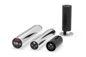
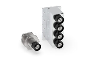
Model NW, Model RFA, Model TR, Model VNW Transducer and TriWheel™ Load Cell (6 Pin)
To verify load cell integrity, unplug the transducer cable at the controller/indicator and use an ohm-meter to measure the resistance at the connector on the cable. Measure between pins A,B, and A,C. Also measure between pins D,E and D,F. In each case the resistance should be about 100 ohms (100 ohms nominal w/Std excitation, 200 ohms nominal w/XR excitation). Measure the resistance between any pin and the outside of connector. The meter should read infinite resistance. Apply a force to the roll by hand or by using a rope and a weight, in the direction of the tension force and maintain it while again measuring between pins A,B and A,C. Repeat while measuring between pins D,E and D,F. The resistance should be only a few ohms different from before. If you see any incorrect readings, disconnect the cable from the transducer and repeat the checks at the connector on the transducer.
| Pair of Pins | Standard Excitation (5 VDC) | Extended Range (10 VDC) |
| Pin A (white) to Pin B (black) | 100 ohms | 200 ohms |
| Pin A (white) to Pin C (red) | 100 ohms | 200 ohms |
| Pin D (green) to Pin E (blue) | 100 ohms | 200 ohms |
| Pin D (green) to Pin F (brown) | 100 ohms | 200 ohms |
| Pin B (black) to to Pin C (red) | 200 ohms | 400 ohms |
| Pin E (blue) to Pin F (brown) | 200 ohms | 400 ohms |
| Any Pin to Body of connector | Infinite | Infinite |
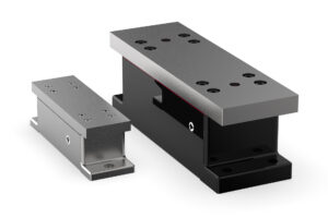
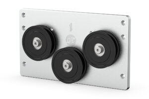
Model LT Low Tension Transducer (6 Pin)
To verify load cell integrity, unplug the transducer cable at the controller/indicator and use an ohm-meter to measure the resistance at the connector on the cable. Measure between pins A,B, and A,C. Also measure between pins D,E and D,F. In each case the resistance should be about 800 ohms (800 ohms nominal). Measure the resistance between any pin and the outside of the connector. The meter should read infinite resistance. Apply a force to the roll by hand or by using a rope and a weight, in the direction of the tension force and maintain it while again measuring between pins A,B and A,C. Repeat while measuring between pins D,E and D,F. The resistance should be only a few ohms different from before. If you see any incorrect readings, disconnect the cable from the transducer and repeat the checks at the connector on the transducer.
| Pair of Pins | Resistance |
| Pin A (white) to Pin B (black) | 800 ohms |
| Pin A (white) to Pin C (red) | 800 ohms |
| Pin D (green) to Pin E (blue) | 800 ohms |
| Pin D (green) to Pin F (brown) | 800 ohms |
| Pin B (black) to Pin C (red) | 1600 ohms |
| Pin E (blue) to Pin F (brown) | 1600 ohms |
| Any Pin to Body of Connector | Infinite |
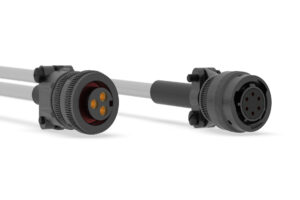
Cable Testing
To check wire continuity in cables, connector sockets and associated wire colors are listed below.
| Connector Socket Letter | Wire Color |
| Socket A | White |
| Socket B | Black |
| Socket C | Red |
| Socket D | Green |
| Socket E | Blue |
| Socket F | Brown |