WHAT IS A TENSION LOAD CELL?
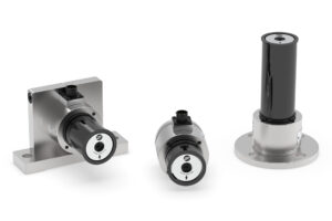
A tension load cell is a type of tension sensor that is used to measure the strain (or force) of a wide variety of materials used in roll-to-roll manufacturing and the converting industry. Specifically, tension load cells – also called tension transducers, are designed to measure the tension or pulling force of web, wire, cable and composite filament or laminate materials. Tension load cells are typically made of metal such as steel and aluminum and consist of a body or “load sensor” that is attached to a roller or pulley system that accepts the force exerted by a material wrapping the appendage.
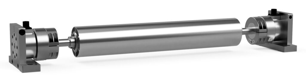
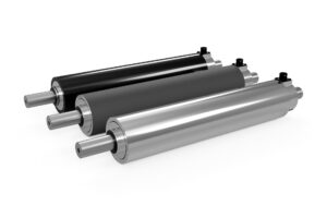
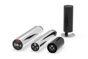
A pair of cartridge load cells paired with a dead shaft idler roll
Industries that use tension load cells include paper, film, foil, printing, aerospace, textiles, non-wovens, pharmaceuticals, automotive and packaging. Tension load cells can also be used in construction and transportation for equipment such as crane scales, hoist and winch systems, and other heavy-duty equipment to measure the weight of loads being lifted or moved.
SIZING A TENSION LOAD CELL
The amount of force transferred to the load cells can be determined by the amount of tension exerted on the material, degrees of contact on the roller assembly (wrap angle), force direction (up, down, horizontal or somewhere in between) and weight of the roller assembly. While sizing tension load cells can sometimes involve complex calculations, if roll weight is not too extreme it may be possible to arrive “in the ballpark” by applying some simple calculations. For example, in practical use a 180 degree material wrap around an idler roll (or pulley) generates twice as much directional force as the tension strain traversing the material. Therefore, if a tension measurement system must operate in the 0-100 lb (0-450 N) range, a 200 lb load cell system should be selected to accommodate the resulting net force.
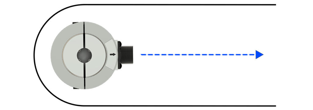
Material wrapping 180 degrees with resulting force direction
This example is a general approach to determining a load rating when two force variables are known. However, it is recommended that each tension sensing application be reviewed by a qualified applications engineer to help account for all variables and ensure that the system is configured to provide optimum performance, reliability and safety of the machine operator.
SENSING TECHNOLOGY
Over time, tension load cell technology has evolved in it’s approach to produce both linear and repeatable signals. Some older systems used a strictly mechanical approach, measuring air or hydraulic pressure to correlate to a force reading. Those systems were prone to calibration drift associated with inconsistent mechanical stiction, and component wear and quickly fell out of favor as lower-maintenance, solid-state solutions began to come to market.
Today’s load cell technology leverages strain gauges that operate with minimal mechanical movement. Typically, the process involves the bending or “deflection” of a metal “sensing beam.” When the strain gauge (adhered to the surface of the beam) deflects, it outputs an electrical signal that is proportional to the force input. This signal is received by a calibrated electronic interface and is converted into a scaled analog or digital output that can be processed by a closed-loop controller or displayed on an operator read-out (HMI).
FOIL vs SEMICONDUCTOR STRAIN GAUGES
The two most common strain gauges used in tension load cells are foil and semiconductor (also called silicon strain gauges). Foil gauges are inexpensive to acquire, but come with a few tradeoffs. The technology requires more beam deflection to provide sufficient signal output, often bringing the beam closer to the limit of plastic deformation. This characteristic makes the load cell design more susceptible to damage during overload conditions, sometimes resulting in failure or reduced overall service life. The lower cost, shorter service life and reduced overall performance of foil gauge load cells has helped establish the reputation of being a “commodity part” by experienced controls engineers.
While semiconductor strain gauge load cells are more expensive, the cost of the gauge is not the only contributing factor. Sensing beams are pre-treated with coatings and cured in ovens to ensure maximum planar adhesion of the gauge. The gauges are then installed and tested by highly-trained technicians under controlled conditions.
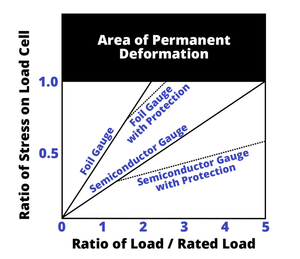
The semiconductor technology is so sensitive that only a few thousands of an inch movement are required to output a signal that is up to 33X more powerful than foil gauge. In industrial environments where EMI exists in abundance, high signal strength is the key to ensuring reliable performance and maximum output resolution. The minimal deflection requirement of semiconductor strain gauge technology also works in synergy with heavy-duty mechanical stops that safeguard the load cells from damage during overload incidents.
The reliability and performance of a properly designed semiconductor gauge tension load cell simply cannot be matched by foil gauge. For this reason, DFE backs each load cell with a 5 year warranty and predicts an average lifespan of 15 to 20 years under typical operating conditions.